Today we will discuss
arduino serial communication. So before go further we should know something
about what is serial communication? We know that the term communication refer
to the information shearing between two devices. It can be done by two method.
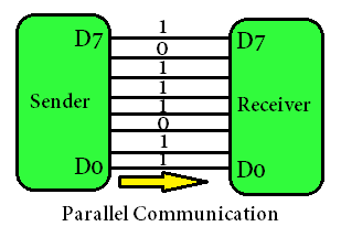
Parallel
communication: Data or information
send parallel pattern from sender to receiver. Let’s 8 bit parallel
communication means 8 bit information reached from sender to receiver at once.
Generally this type of communication done
between small distances.
Serial
communication: Data or information send
serial pattern from sender to receiver. Let’s 8 bit serial communication means
8 bit information reached from sender to receiver serially one by one.
Serial communication
done between long distances.

Now we know basic
concept of Serial communication. Let’s come to our main topic that is arduino
serial communication. For arduino serial communication, we have to clear some
question first.
How we do arduino
serial communication?
Which pins are
responsible for arduino serial communication?
Answer of first
question is we do know arduino serial communication by UART port. UART stands
for universal asynchronous receiver-transmitter.
UART is a computer
hardware device for asynchronous serial communication. The main advantage of
UART is we can configure the bit pattern and transmission speed also.
Now answer of second
question is pin numbers 0 and 1 are used for serial communication in arduino
uno board. We can see RX (receive) and TX (transmit) are written over the
board.

PROJECT DESCRIPTION:
To make easily
understand the process, we simulated the based project on proteus software. Were the LCD
is interfaced to the arduino board and virtual serial terminal. Now after writing proper
arduino program, we can see whatever we write in virtual terminal. It will
display in Lcd. It proved that whatever we send the data through virtual
terminal. It will received TX and RX pin and display to LCD.
The project description is simple as shown in the circuit diagram made with proteus
software. If you need some knowledge on interfacing LCD with arduino do study the basics.

simulation diagram
Get the simulation code below using mickro c pro compiler .
Embedded
C Code
// Name : Arduino serial communication
// Author : Engr. Okoh
// Date : 29-01-18
// Website : www.sltech360.blogspot.com
#include // initialize the library with the
numbers of the interface pins
LiquidCrystal lcd(12, 11, 5, 4, 3, 2);
void setup()
{
// set up the LCD’s number of columns and rows:
lcd.begin(16, 2);
// initialize both serial ports:
Serial.begin(9600);
}
void loop() {
if (Serial.available()) {
unsigned int inByte = Serial.read();
Serial.write(inByte);
lcd.write(inByte);
lcd.leftToRight();
}
}PLEASE DO SUBSCRIBE TO OUR FACEBOOK CHANNEL


No comments:
Post a Comment