Interfacing Ultrasonic Sensor HC-SR04 with Arduino Uno R3
Here we come with the topic Interfacing Ultrasonic Sensor HC-SR04 with Arduino Uno R3. After getting the interfacing successfully lots of projects window will be open for us. In my earlier post we saw that how to interface LM35 analog temperature sensor with Arduino at “Arduino based digital thermometer”. So to know the Interfacing Ultrasonic Sensor HC-SR04 with Arduino Uno R3, first we have to know about What is an Ultrsonic sensor? And how it work?
HC-SR04 module:
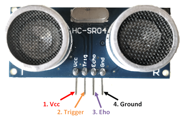
The ultrasonic sensor also known as distance measuring sensor provides 2cm to 4m of non-contact measurement functionality with a ranging accuracy that can reach up to 3mm. Each HC-SR04 module includes an ultrasonic transmitter, a receiver and a control circuit. There are only four pins that you need to worry about on the HC-SR04: VCC (Power), Trigger, Echo, and GND (Ground). Interfacing this Sensor with Arduino is easy.
Apparatus required : –
- Arduino Uno R3 (ATMega328P) with Arduino Cable
- Ultrasonic Sensor HC-SR04 Module
- 4 Male-to-Female Jumper Wires & 8 Male-to-Male Jumper wires
- Breadboard
- Buzzer
- LED
- Battery 9V
- On-Off switch
Circuit Connection : –
As we already know that there are 4 pins in the Ultrasonic Sensor HC-SRO4 Module and 28 pins in the Arduino Uno R3. First we have to set up the sensor module in the breadboard. Then we have to connect the 4 pins with one end of each of the male-to-female jumper wires. The other ends of the jumper wires coming out of the Vcc & GND pin are connected on the two separate sides of the breadboard & the other two ends coming out of the Trigger & Vcc pins are connected elsewhere on the breadboard. Then we connect two male-to-male jumper wires with the points where the Trigger & Echo pins have been connected & connect their other two ends with the Digital pins (pin7 with Trigger & pin8 with Echo) of the Arduino device. Then we take another two male-to-male jumper wires & connect them with the 5V (Vcc pin) & GND pin of the Arduino device & connect their other two ends at those points where we have placed the Vcc & GND pins of the Sensor Module. This simply means we setting up a common ground for all the GND pins.

Then we set up the Buzzer & LED on the breadboard. We connect the positive ends of the Buzzer & LED with the Arduino at the Digital pins (pin9 with Buzzer & pin3 with LED) by two male-to-male jumper wires. Then we connect the negative pins of the Buzzer & LED at the common ground where the GND pins of the Arduino & Sensor Module have been connected.
Finally we connect the 9V Battery & the switch with the breadboard.
Hence our circuit connection is complete. Now we have to develop the program for Arduino interfacing with Ultrasonic Sensor. After developing the program we connect the Arduino cable with the Arduino & the pc.
Program Execution : –
The program to be uploaded in the Arduino device is written below. It has been verified accordingly in the Arduino app in the pc.


Comments
Post a Comment