Automatic Room Lights using Arduino and PIR Sensor
In this project, we
will see the Automatic Room Lights using Arduino and PIR Sensor, where the
lights in the room will automatically turn ON and OFF by detecting the presence
of a human.
Such Automatic Room
Lights can be implemented in your garages, staircases, bathrooms, etc. where we
do not need continuous light but only when we are present.
Also, with the help
of an automatic room light control system, you need not worry about electricity
as the lights get automatically off when there is no person.
So, in this DIY
project, we have implemented Automatic Room Lights using Arduino and PIR
Sensor.
Over view
Automatic Room Lights
System using Arduino is a very useful project as you need not worry about
turning on and off the switches every time you want to turn on the lights. The
main components of the Automatic Room Lights project are Arduino, PIR Sensor
and the Relay Module.
Out of the three
components, the PIR Sensor is the one in focus as it is the main device that
helps in detecting humans and human motion.
In fact, the
Automatic Room Lights project can be considered as one major application of the
PIR Sensor. A similar concept is being already implemented in automatic toilet
flush valves, hand dryers, etc.
Circuit Diagram of
Automatic Room Lights using Arduino
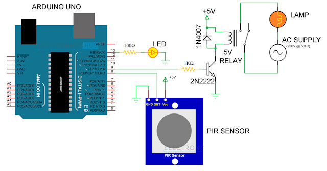
The following image
shows the circuit diagram of the project implemented using Arduino UNO, PIR
Sensor and a Relay Module.
If you do not have a
relay module, you can make one yourself using very simple hardware. The
following circuit diagram shows the project being implemented with the help of
discrete components for the Relay Module.
CAUTION: The project
involves connection with 230V AC Mains (or 110V, depending on where you
live!!!). Be extremely careful when connecting the bulb and Relay to mains
supply. If you are unfamiliar with the connections, I strongly recommend having
an adult supervision (or an expert supervision).
Components Required
for Automatic Room Lights using Arduino
• Arduino UNO
• PIR Sensor
• 5V Relay Module (Relay Board)
• LED
• 100Ω Resistor (1/4 Watt)
• Connecting Wires
• Breadboard
• Power Supply
If you do not have a
Relay Module, use the following components:
• 5V Relay
• 2N2222 (or BC547) NPN Transistor
• 1N4007 PN Junction Diode
• 1KΩ Resistor (1/4 Watt)
Component Description
PIR Sensor
We have already seen
about PIR Sensor in the PIR Motion Sensor Tutorial and also implemented in a
variety of projects like Home Security System and Automatic Door Opener.
Relay Module
A Relay Module is a
very useful component as it allows Arduino, Raspberry Pi or other
Microcontrollers to control big electrical loads. We have used a 2-channel
Relay Module in this project but used only one relay in it. The relay module
used in this project is shown below.
In order to control a
single relay on the board, we need to use three pins of the relay module: VCC,
GND and IN1.
NOTE: The relay
module used in this project is as active LOW one i.e. when the IN1 pin is HIGH,
the relay is OFF and when it is LOW, the relay is activated. This point is
important while programming the Arduino UNO.
Circuit Design
PIR Sensor’s Data OUT
Pin is connected to Arduino’s Digital I/O Pin 8. An LED is connected to pin 13
of Arduino to indicate whether the light is turned ON or OFF.
The IN1 pin of the Relay
Module is connected to Pin 9 of Arduino. A bulb is connected to mains supply
through relay. One terminal of the bulb is connected to one wire of the mains
supply. The other terminal of the bulb is connected to the NO (Normally Open)
contact of the Relay Module.
COM (Common) contact
of the Relay is connected to the other wire of the mains supply. Be careful
when connecting this part of the project.
Code:
Embedded C Code
int in1 = 9;
int sensor = 8;
int led = 13;
unsigned long t=0;
void setup()
{
Serial.begin(9600);
pinMode(in1, OUTPUT);
pinMode(sensor, INPUT);
pinMode(led, OUTPUT);
digitalWrite(in1,HIGH);
digitalWrite(led,LOW);
while(millis()<13000 span="">
{
digitalWrite(led,HIGH);
delay(50);
digitalWrite(led,LOW);
delay(50);
}
digitalWrite(led,LOW);
}
void loop()
{
digitalWrite(in1,HIGH);
digitalWrite(led,LOW);
if(digitalRead(sensor)==HIGH)
{
t=millis();
while(millis()<(t+5000))
{
lWrite(in1,LOW);
digitalWrite(led,HIGH);
if((millis()>(t+2300))&&(digitalRead(sensor)==HIGH))
{
t=millis();
}
}
}
}
}
Working of the
Project
The Automatic Room
Lights using Arduino and PIR Sensor is a simple project, where the lights in
the room will automatically turn on upon detecting a human motion and stay
turned on until the person has left or there is no motion.
Working of this
project is very simple and is explained here.
Initially, when there
is no human movement, the PIR Sensor doesn’t detect any person and its OUT pin
stays LOW. As the person enters the room, the change in infrared radiation in
the room is detected by the PIR Sensor.
As a result, the
output of the PIR Sensor becomes HIGH. Since the Data OUT of the PIR Sensor is
connected to Digital Pin 8 of Arduino, whenever it becomes HIGH, Arduino will
activate the relay by making the relay pin LOW (as the relay module is an
active LOW module).
This will turn the
Light ON. The light stays turned ON as long as there is movement in front of
the sensor.
If the person takes a
nap or leaves the room, the IR Radiation will become stable (there will be no
change) and hence, the Data OUT of the PIR Sensor will become LOW. This in turn
will make the Arduino to turn OFF the relay (make the relay pin HIGH) and the
room light will be turned OFF.
Applications
I’ve already
mentioned a few applications of the Automatic Room Lights concept. Some of them
are:
• Garage Lights
• Bathroom Lights
• Hand Dryers
• Toilet Flushers
• Security Lights


Thanks for sharing such a useful information.
ReplyDeleteHome Automation Company Delhi