Posts

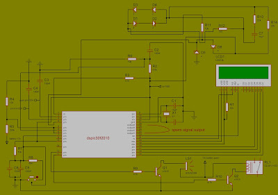
DSPIC30F2010 PURE SINE WAVE INVERTER

Image
The circuit am sharing today is an inverter circuit which can also charge every inverter/solar battery with a selected charge current. As said earlier, the inverter / circuit runs on a digital signal processing micro-controller made by micro-chip.  Today i will give the conclude part of the long waited circuit . CIRCUIT DIAGRAM PART ONE PART TWO PART THREE COMPLETED PART HEX FILE  :020000003229A3 :08000800D5000308D3000A082B :10001000D4008A01831A0D28182855088312D500A8 :10002000831653088312D300831654088312D40016 :10003000A21A212881308316920083122213C5014F :10004000312803110B305902031D312803114808D0 :100050000319221303193128BF0022178316920AAD :100060008312031101305902031D8128411C5528B8 :1000700007119701950196010C30970041108710E8 :1000800087154208C300C1184115C11C4111A218AF :100090006628C70B411DA214411D6628CD034030C0 :1000A0004D024030031CCD008128071197019501B6 :1000B00096010C3097008714871141144508C3003E :1000C000C1184115C11C4111A21C81280310C30C89 :1000D0000310C30C411D77284308CD0240...

MOSFET driver TLP250 for dspic30f2010

Image
TLP250 is an isolated IGBT/Mosfet driver IC.  The input side consists of a GaAlAs light-emitting diode. The output side gets a drive signal through an integrated photodetector. Therefore, the main feature is electrical isolation between low and high power circuits. It transfers electrical signals optically via light. Users can use it to drive gate terminal of high voltage switches in both configurations such as high side and low side drive. It is available as an 8-pin DIP package. We have already posted an article on non-isolated gate driver IR2110. MOSFET driver IR2110  is used to drive n-channel or p-channel MOSFETs in the high side and low side. What is a MOSFET/IGBT driver? It is the main component of power electronics circuits. Mosfet driver is dedicated to integrated circuits that are used to drive gate terminal of power switches both in the low side and high side configuration. To know more about gate driver check the following article: What is MOSFET gate driver? Pinou...

DSPIC30F2010 PART2

Image
LM324 DESCRIPTION These devices consist of four independent high-gain frequency-compensated operational amplifiers that are designed specifically to operate from a single supply over a wide range of voltages. Operation from split supplies also is possible if the difference between the two supplies is 3 V to 32 V (3 V to 26 V for the LM2902 device), and Vcc   is at least 1.5 V more positive than the input common-mode voltage. The low supply-current drain is independent of the magnitude of the supply voltage. Applications include transducer amplifiers, dc amplification blocks, and all the conventional operational-amplifier circuits that now can be more easily implemented in single-supply-voltage systems. For example, the LM124 device can be operated directly from the standard 5-V supply that is used in supplies. digital systems and provides the required interface electronics, without requiring additional ±15-V C1815 Silicon NPN Epitaxial Transistor Description : The C1815 i...

INVERTER DESIGN USING DSPIC30F2010 (part 1)

Image
OBJECTIVE : To know how the various component function so as to produce the appropriate programming for it to produce and spwm for MOSFET drivers. COMPONENT REQUIRED: 1.      Resistor of different value 2.      Capacitor of different value 3.      Dispic30f2010 microcontroller 4.      Crystal oscillator 5.      Voltage regulator 6.      Diode 7.      Lcd(16x2) 8.      Transistor EXPLANATION Crystal oscillator A crystal oscillator is an electronic oscillator circuit that uses the mechanical resonance of a vibrating crystal of piezoelectric material to create an electrical signal with a precise frequency. Voltage regulator A voltage regulator is a system designed to automatically maintain a constant voltage level. Resistor  A resistor is a passive two-terminal electrical component that implements electrical resistance as a cir...

Interfacing Ultrasonic Sensor HC-SR04 with Arduino Uno R3

Image
Here we come with the topic Interfacing Ultrasonic Sensor HC-SR04 with Arduino Uno R3. After getting the interfacing successfully lots of projects window will be open for us. In my earlier post we saw that how to interface LM35 analog temperature sensor with Arduino at “Arduino based digital thermometer”. So to know the Interfacing Ultrasonic Sensor HC-SR04 with Arduino Uno R3, first we have to know about What is an Ultrsonic sensor? And how it work? HC-SR04 module: The ultrasonic sensor also known as distance measuring sensor provides 2cm to 4m of non-contact measurement functionality with a ranging accuracy that can reach up to 3mm. Each HC-SR04 module includes an ultrasonic transmitter, a receiver and a control circuit. There are only four pins that you need to worry about on the HC-SR04: V CC  (Power), Trigger, Echo, and GND (Ground). Interfacing this Sensor with Arduino is easy. Apparatus required  : – Arduino Uno R3 (ATMega328P) with Arduino Cable Ultras...

pure sinewave inverter

Image
What is an Inverter? An inverter converts the DC voltage to an AC voltage. In most cases, the input DC voltage is usually lower while the output AC is equal to the grid supply voltage of either 120 volts, or 240 Volts depending on the country. The inverter may be built as standalone equipment for applications such as solar power, or to work as a backup power supply from batteries which are charged separately. The other configuration is when it is a part of a bigger circuit such as a power supply unit, or a UPS. In this case, the inverter input DC is from the rectified mains AC in the PSU, while from either the rectified AC in the in the UPS when there is power, and from the batteries whenever there is a power failure. There are different types of inverters based on the shape of the switching waveform. These have varying circuit configurations, efficiencies, advantages and disadvantages An inverter provides an ac voltage from dc power sources and is useful in powerin...

DSPIC30f2010 PURE SINE INVERTER CIRCUIT WITH CHARGER

Image
THE DSP30f2010 INVERTER .  The circuit am sharing today is an inverter circuit which can also charge every inverter/solar battery with a selected charge current. As said earlier, the inverter / circuit runs on a digital signal processing micro-controller made by micro-chip. You can download the datasheet by clicking Here. The inverter has the following functions and protections . 1. Ability to work as inverter or UPS. 2. MOSFET protection system using LM324 3. Better battery charging algorithm 4. Low voltage protection 5. high voltage Protection 6. Works on 12V, 24V, 48V, 96V, 120V 7. Overload protection 8. Over charging protection 9. Over battery protection 10. Load display 11. Cooling fan failure detection and tripping with alarm 12. NTC sensor failure detection and tripping with alarm 13. Over Temperature protection 14. The circuit board can be used to repair all pure sine inverters. 15. Set your own maximum load, charging current and...

PROGRAMMING WITH MPLAB ASM

Image
Overview Many of the projects on the site already provide the necessary HEX file to program into the PIC.  In this case all you need to do is download the HEX file and program it into the PIC,  you do not need to do anything else.  Other projects on the site allow you to modify or edit the source code to suit your own needs.  With these projects it is necessary to assemble the modified source code to create a new HEX file. To turn the source code into something that can be programmed into the actual PIC microcontroller chip you need to assemble the code.  This is done using the MPASM assembler which takes the source files and creates a HEX file that your programmer hardware can write into the PIC chip. You can do this by opening the source code files in the MPLAB IDE program and using the Quickbuild option to generate the HEX file.  If you have a PICkit2 prog...